
CAN Ecosystem
-
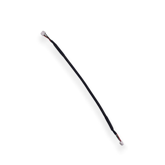
Shielded CAN Cable
Regular price From £3.00 GBPRegular priceUnit price per -
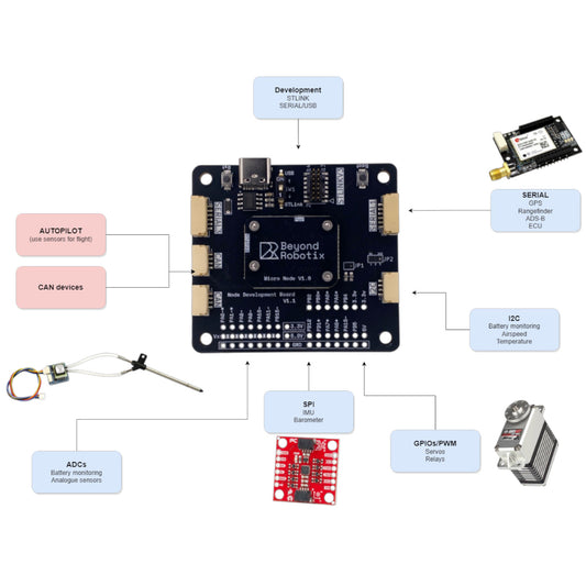
Micro CAN Node Development set
Regular price From £30.00 GBPRegular priceUnit price per -
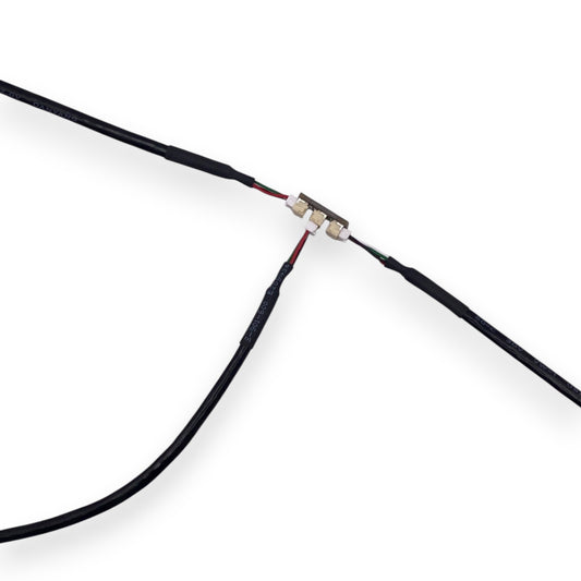
CAN + I2C T Junction
Regular price £3.60 GBPRegular priceUnit price per

CAN Wiring & Accessories
-
Shielded CAN Cable
Regular price From £3.00 GBPRegular priceUnit price per -
CAN + I2C T Junction
Regular price £3.60 GBPRegular priceUnit price per

Build Faster, Integrate Smarter
The Beyond Robotix CAN ecosystem is designed to reduce development complexity and accelerate integration. Instead of dealing with multiple wiring harnesses and fragmented communication methods, developers can use a unified CAN architecture to connect sensors and modules quickly and efficiently.
Minimal firmware complexity
Sensor nodes can be built in under 100 lines of code
Daisy-chain wiring
Scalable and lightweight network expansion
Plug-and-play architecture
Simplify integration across UAV platforms
Consistent communication layer
One bus for all critical system data